Our Blog

undefined

Part 3 of the Overview of Gas Lift series has procedures for identifying, selecting, and optimizing technical as well as field operations for a gas lift well. Section IIIA reviews the gas lift well candidate related to gas content in the reservoir fluid and a choice of gas lift or pumping. Section IIIB discusses the well completion related to dimensional and clearance considerations and gas lift facility requirements. Section IIIC has guides for kicking off a well and avoiding erosion cutting of the unloading valves. Section IIID provides the procedure to optimize the well once it has kicked off and is operating in the production system.

undefined

In the Part 1 of this Series on Gas Lift History and Basic Well Parameters, an attempt was made to bring into focus the primary “state of affairs” of Gas Lift operations in the USA. Part 2 will discuss basic Gas Lift well casing and tubing components, and their operational function, as well as Choke Flow relationships in Gas Lift wells. In the First Section II.A, Energy and Mass Balance relationships will be used to compute flowing pressure gradients, (dP/dL) (psi/ft) for injected casing gas ((dP/dL)g), and for further documents addressing this subject, multiphase flow in the tubing ((dP/dL)mp). 
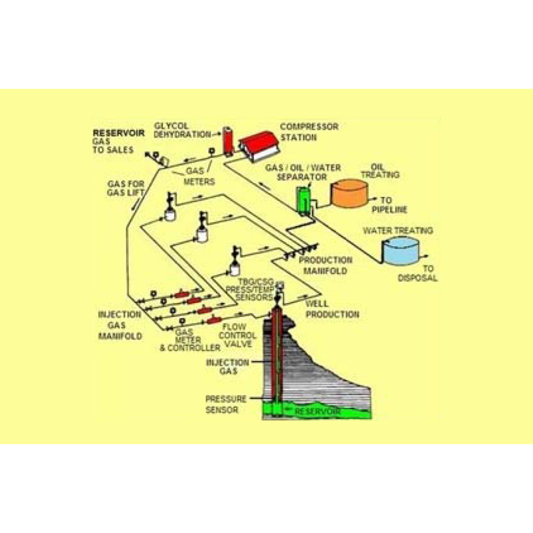
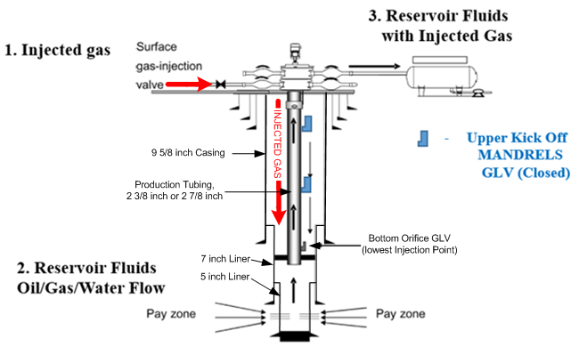
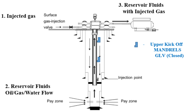
Section II.B will address gas injected at surface into the annular space between production casing and tubing. The injection gas travels down the annular space on its way to either a “kickoff “gas-lift” valve located in a tubing MANDREL with an Injection Pressure Operated gas lift valve (IPO), or to the bottom Orifice GLV. Calculations will be performed to determine injected gas annular flow vs. pressure loss related to the 9 5/8” casing and either the 2 3/8”, or 2 7/8” production tubing. The flow is then considered in the annular space between the 7” liner and either the 2 3/8’’, or 2 7/8’’ production tubing. Casing gas flow does not encounter the 5” liner. Physical dimensions for these selections will be addressed. Section II.C presents the basic, single phase gas flow performance characterization related to CHOKE FLOW in the Gas Lift Valve. Once a valve has been fitted with a choke (orifice) size, the flow performance of a choke will follow the mass, and energy balance relationships related to isentropic gas expansion. This flowing condition for the choke MUST be selected in its transitional, sub-critical flow region so that additional changes to injection gas flowrates may be made if called for. It is essential to design the final Orifice GLV so that operation near, or in the Critical Regime (Sonic Flow) is avoided. A numerical example will be presented to illustrate the direct application Casing / Liner Gas injection data with the corresponding IPR Tubing Gas Lift Valve with installed CHOKE dimensions.

undefined

In this Part 1 presentation of the initial Gas – Lift series, and effort has been made to provide for initial orientation regarding the important Gas – Lift history, initial background, initial production efforts, Gas – Lift components, and design criteria. Oil and Gas production has been an integral part of the World’s energy based economy for over 160 years. Improvements in new GLV designs were implemented after the 1940’s. In all GL applications, however, the pressure and volume of the injection gas was difficult to control due to the limited numerical models available to predict the Valves’ “CHOKE PERFORMANCE”. Injection Gas is injected down the tubing casing annulus through a series of “kick – off” (well flow initiation) Mandrels containing the applicable GLV, or the standing GLV at the bottom of the tubing string. The Mandrel is a single section of the production tubing string that allows insertion of the selected GLV. The solution Gas Oil Ratio, Rs, (GOR related in SCF/STB) is the gas that the reservoir oil has in solution in an oil reservoir at a specific pressure and temperature. This gas is liberated as the formation fluid is transported to the surface. The amount of flowing free gas will depend on the oil rate. The Oil Formation Volume Factor, Bo (Bbl/STB), also plays an important role in the solution gas being liberated by flowing pressures and temperatures.

undefined

In some cases, a choke/line heater is required at the wellsite to deal with the large JT expansion cooling effect experienced by choked high-pressure wells, especially during start-up. This is a somewhat different application than prevention of hydrates in the GGS but there are some common aspects to the equipment utilized. First, the hydrate temperature of the flowing wellstream is estimated. From Figure 1, for 0.65 SG gas and assuming any free water present is condensed/fresh water, the estimated hydrate temp at an assumed average GGS pressure of 1,100 psig is ~ 65 F.

The Diffusivity Equation

undefined

The theory of well testing begins with an understanding of fluid flow in porous media. In this article, the continuity equation, Darcy’s law, and equation of state for a slightly compressible liquid are used to develop the diffusivity equation, describing single-phase flow of a slightly compressible liquid.


Filters Contact Us Menu 0 $0.00
Top